
IR Box construction guide Integrate the PC infrared receiver into a plastic box
IR Box introduction …
The infrared receiver kits had to go without a enclosure so far and it is time to change this. Now there is the new IR box available, where one can insert for example the PCB of the brand-new USB Ultra infrared receiver v2.0, in order to protect the electronic devices and to get a more beautiful construction for the PC or HTPC. Of course it is also possible to integrate different IR receivers into the small black plastic box, this small modding guide is just an example for the latest USB IR solder guide.Here is the USB Ultra IR v2.0 solder guide.
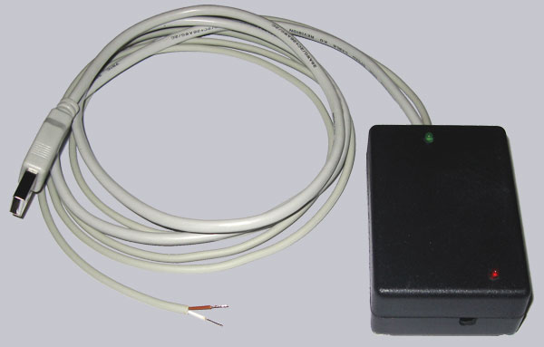
The IR Box …
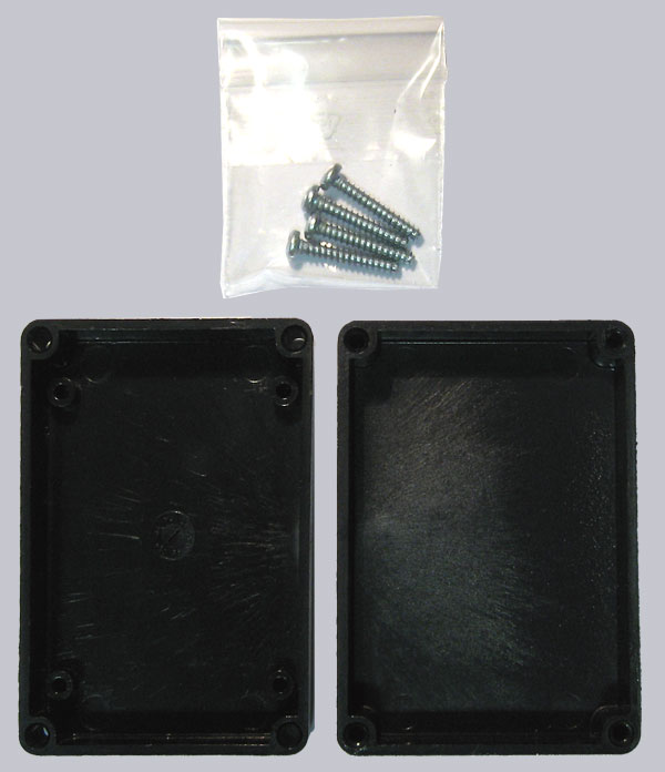
Here is a picture of the two IR Box case half shells with the 4 screws to close the chassis, as it e.g. available as IR Box kit in the Fanshop.
The tools …
Of course some tools are necessary. For example: – a small round file (or mini drill) – 3mm drill and a larger drill or countersunk drill to burr – screwdriver for recessed head screws – Ruler – Pencil or scriber – optionally a cable strap to fasten the cable inside of the case.
Place the PCB into the box …
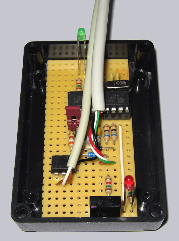
First we place the PCB (printed circuit board) loosely into the bottom half shell. One recognizes the distance holder in the bottom half shell, which we do not need for our small PCB size.
Prepare the drillings for the light emitting diodes …
Then we measure the horizontal and vertical distances of the two LEDs and transfer it 1:1 to the cover.
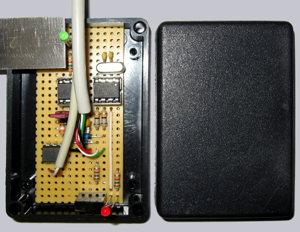
Mark these points only a little bit with a pencil or a scriber on the frame cover, so that one cannot see the markings after drilling on the cover. Alternatively one can mark and drill it from the inside and remove the burr outside.

Who can’t find the two markings, can recognize them more clearly on the next picture.
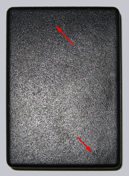
Now we can drill in each case a small 3mm hole at the two markings. Who has a peening tool can place a center before, because the drill can slip away on the plastic cover, very fast.
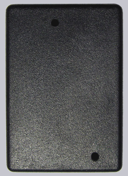
Prepare the drillings for the cable and the infrared receiver …
Now we place the PCB once again to the bottom case half of the IR box to mark the entry position for both cables on one side and on the other side the lens of the TSOP infrared receiver. The space for the lens may be relatively small, but not smaller than approx. 5×5 millimeters to ensure a good range.

Now we can file the two markings with a round file. A Dremel is not necessary for these small notches, but of course it’s possible to use it instead of the round file.
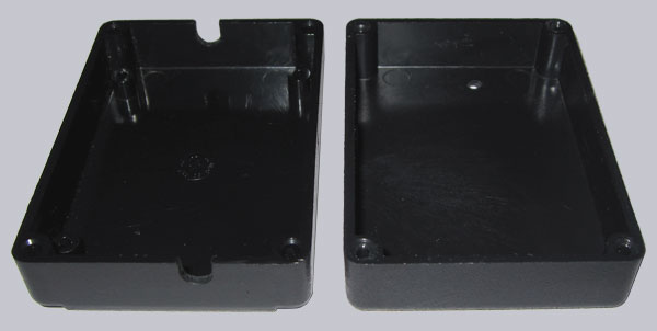
Now we place the infrared receiver into the IR box and screw down the box with the 4 provided screws. Optionally it’s possible to fasten the cable within the IR box with a cable strap, to prevent that it can be pull out from the case. The PCB of the new USB Ultra IR receiver 2.0 does not slip around without further attachments, because the two LEDs press and fix the PCB to the case bottom. Who would like to insert a smaller circuit board e.g. of the USB IR or USB Ultra IR v1.1 / v1.0 into this IR box, can screw an additional plate to the bottom case half to fix the PCB very easy.
That’s it, the IR receiver is ready to receive your universal remote control signals inside of the nice IR box case.

Discuss in our forum and exchange experiences …

