
Layout, design and features …
Let’s take a closer look at the UPS.

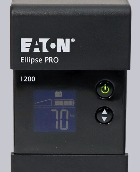
The front looks very clean. Here you can see the LCD and the power button as well as a menu button for selecting various display modes.
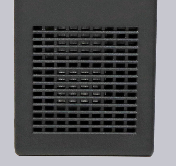
At the front, we see an air intake in the lower area which provides fresh air in the housing.
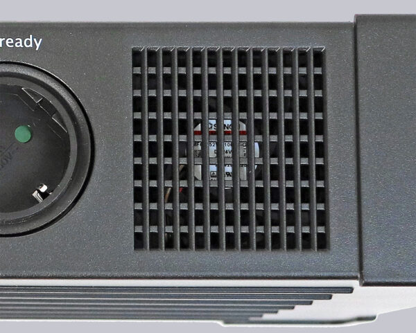
The top contains the four earthed sockets, one of which is PLC-ready. This means that you can connect a powerline adapter to this socket outlet and thus establish a network connection via the household power grid. Depending on the setting, the two Eco-Control sockets can be switched off automatically when the device connected to the master socket is switched off. All sockets have overvoltage protection that offers protection up to 6000 V, 3000 A in accordance with the standard. However, they are not supplied with power from the batteries in the event of a power failure.

On the top we also see a fan grille fitted with a 24 V fan, which transports the warm air out of the housing.
The rear offers a similar picture, but is home to further connections that we would like to discuss here. The previously mentioned master connection and three further safety sockets are located here. All four sockets are supplied with power via the batteries in the event of a power failure.
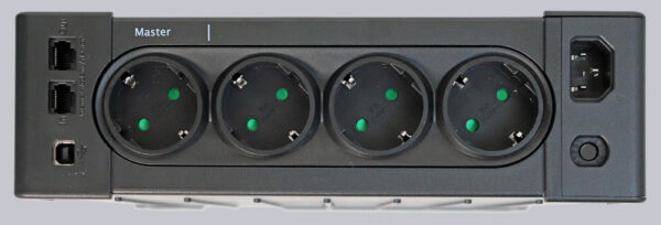
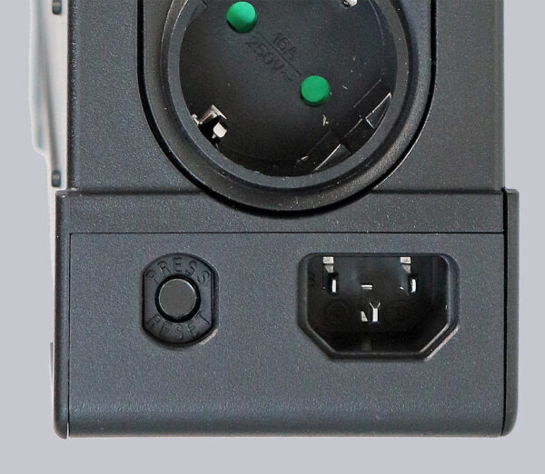
In the lower part we find a 10 A fuse which we can reset by pressing a button and the C14 IEC plug power connection, which we already know from computer power supplies.
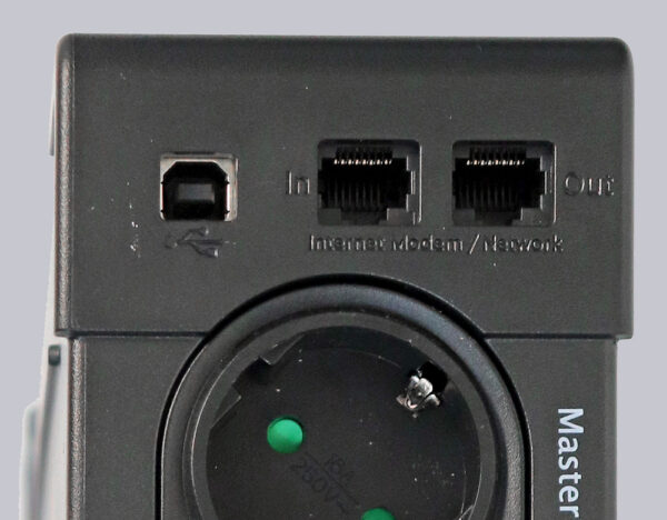
In the upper part we see the USB type-B connection via which the UPS can be managed with a computer. Next to it are the two line connections, which are also able to protect a DSL or network line against overvoltage. When it comes to overvoltage protection, many people forget the telephone or DSL connection, which can fortunately be protected by this UPS by looping the DSL cable through the two 8P8C RJ45 connections. The DSL signal quality was not measurably worse in our test.
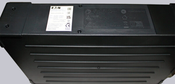
The underside offers a view of the battery compartment and other technical details, which are shown here on a sticker.
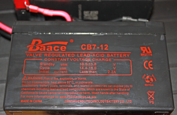
When we open the battery compartment, we immediately see the two rechargeable batteries and the plug connection that must be disconnected before changing them.
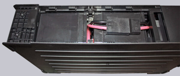
The batteries used are lead-acid batteries with a nominal voltage of 12 V and a capacity of 7 Ah.
Let’s take a look at the sides of the housing, which are closed and therefore offer no further ventilation.
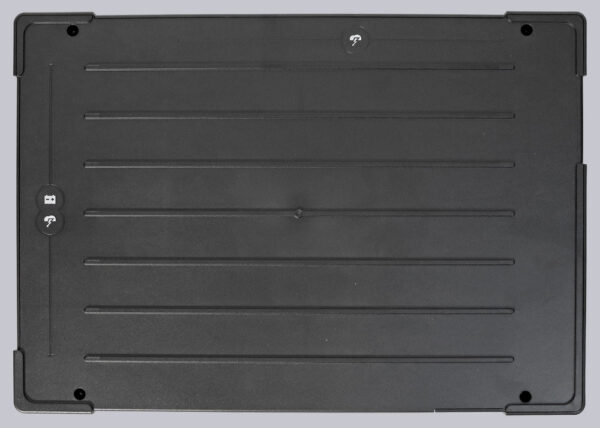
In order for the user to be able to make use of the manufacturer’s warranty, it is necessary that the UPS is not technically modified. This includes the prohibition to open the UPS. Of course, it is permitted to open the bottom cover to replace the batteries. However, as part of our test, we would still like to take a look inside the device to get an overview of the workmanship and quality. After removing the base cover and the batteries, we set about opening the side cover. To do this, the four screws have to be removed and the clips loosened.
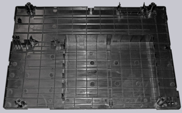
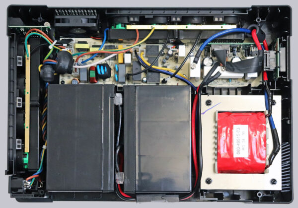
This can only be done from the outside and very carefully. It is best to use a pick or a hard plastic card. We then take a look at the inside of the UPS. You can clearly see the large transformer at the bottom right and all the electronics in the upper area.
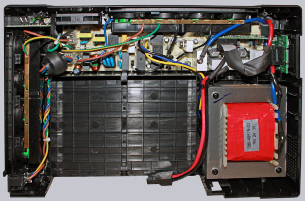
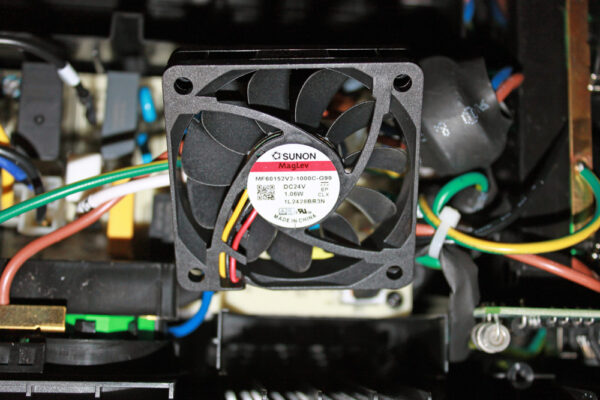
The installed 60x60x15mm fan is a 24V model MF60152V2-1000C-G99 from the Sunon brand, which many people will already be familiar with from other devices used as housing fans.
Looking at the earthing contact strip, we can see that the protective conductor is soldered rather than screwed.
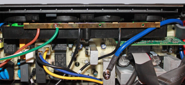
The further processing offers no reason for complaint. No unclean solder joints or excessive use of glue.
Now we come to the installation and commissioning of the Eaton Ellipse Pro 1200VA UPS.
Eaton Ellipse Pro 1200VA Installation …

